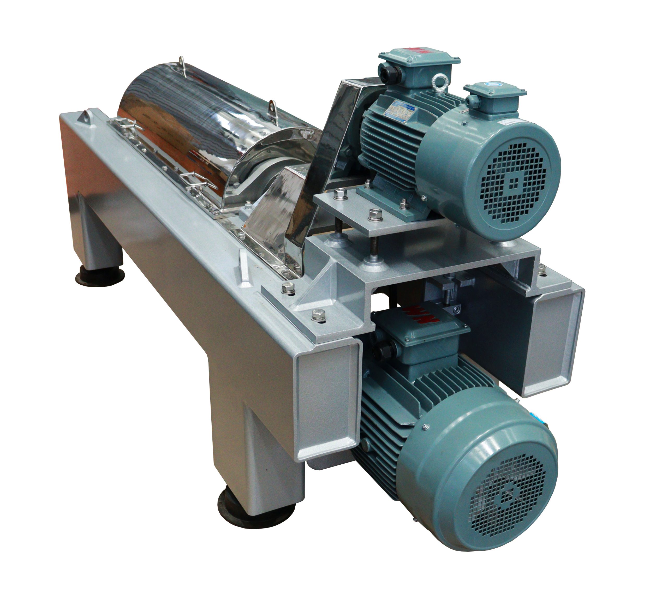
Product Description
The disc stack centrifuge is a versatile device, which may be used for separating solid/liquid mixtures in continuous, semi-continuous and batch configurations (see Figures 1.12 and 1.13). All except some batch-operated machines are able to handle toxic, flammable and volatile feeds at throughputs up to 200 m3 h−1. Liquid-liquid mixtures can be separated and with more sophisticated units a three (two liquid and one solid) phase separation is achievable. In all cases, a sufficient density difference must exist between the phases present in the feed.
Work principle
Inside the rotating drum, there exists a group of disc-shaped components, named discs, which are mutually nested. A very small gap is left between each disc. The suspension (or emulsion) is added to the rotating drum through the feed pipe located at the center of the drum. When the suspension (or emulsion) flows through the gaps between the discs, the solid particles (or droplets) settle onto the discs under the effect of the centrifuge, forming sediment (or liquid layer). The sediment slides along the surface of the discs, detaches from them, and accumulates at the part with the largest inner diameter of the drum. The separated liquid is discharged from the liquid outlet of the drum. The role of the discs is to shorten the settling distance of the solid particles (or droplets) and expand the sedimentation area of the drum. Due to the installation of the discs in the drum, the production capacity of the separator is significantly enhanced. The solid accumulated in the drum is removed manually after the separator is shut down and the drum is disassembled, or discharged from the drum through the slag discharge mechanism without stopping the machine.
After entering the high-speed rotating drum, the turbid liquid enters the disc stack along the channel and forms three dynamic concentric rings under the strong centrifugal force: a small amount of dense solid particles move outward and accumulate on the peripheral wall, forming an outer layer; A dense heavy phase liquid is thrown towards the lower surface of the disc, sliding downwards out of the disc area, forming an intermediate layer; A light phase liquid with lower density moves towards the center of the drum, forming an inner layer. Three groups are discharged from the drum through their respective channels.

Parameters
|
Modle
|
Treatment Capacity
(L/h)
|
Drum Diameter
(mm)
|
Drum Speed
(rpm)
|
Motor Power
(kw)
|
Weight
(kg)
|
Outline Size
(L*W*H)(mm)
|
|
LH270
|
500-1000
|
270
|
7500
|
4
|
420
|
1100*900*1200
|
|
LH360
|
1000-2000
|
360
|
7000
|
11
|
810
|
1400*1100*1500
|
|
LH470
|
2000-6000
|
470
|
6700
|
18.5
|
1600
|
1700*1400*1800
|
|
LH500
|
3000-7000
|
500
|
6500
|
18.5
|
1680
|
1700*1400*1800
|
|
SH270
|
500-1000
|
270
|
7500
|
4
|
420
|
1100*900*1200
|
|
SH360
|
1000-2000
|
360
|
7000
|
11
|
810
|
1400*1100*1500
|
|
SH470
|
2000-6000
|
470
|
6700
|
15
|
1600
|
1700*1400*1800
|
|
SH500
|
3000-7000
|
500
|
6500
|
18.5
|
1680
|
1700*1400*1800
|